
Description
1. Product Description
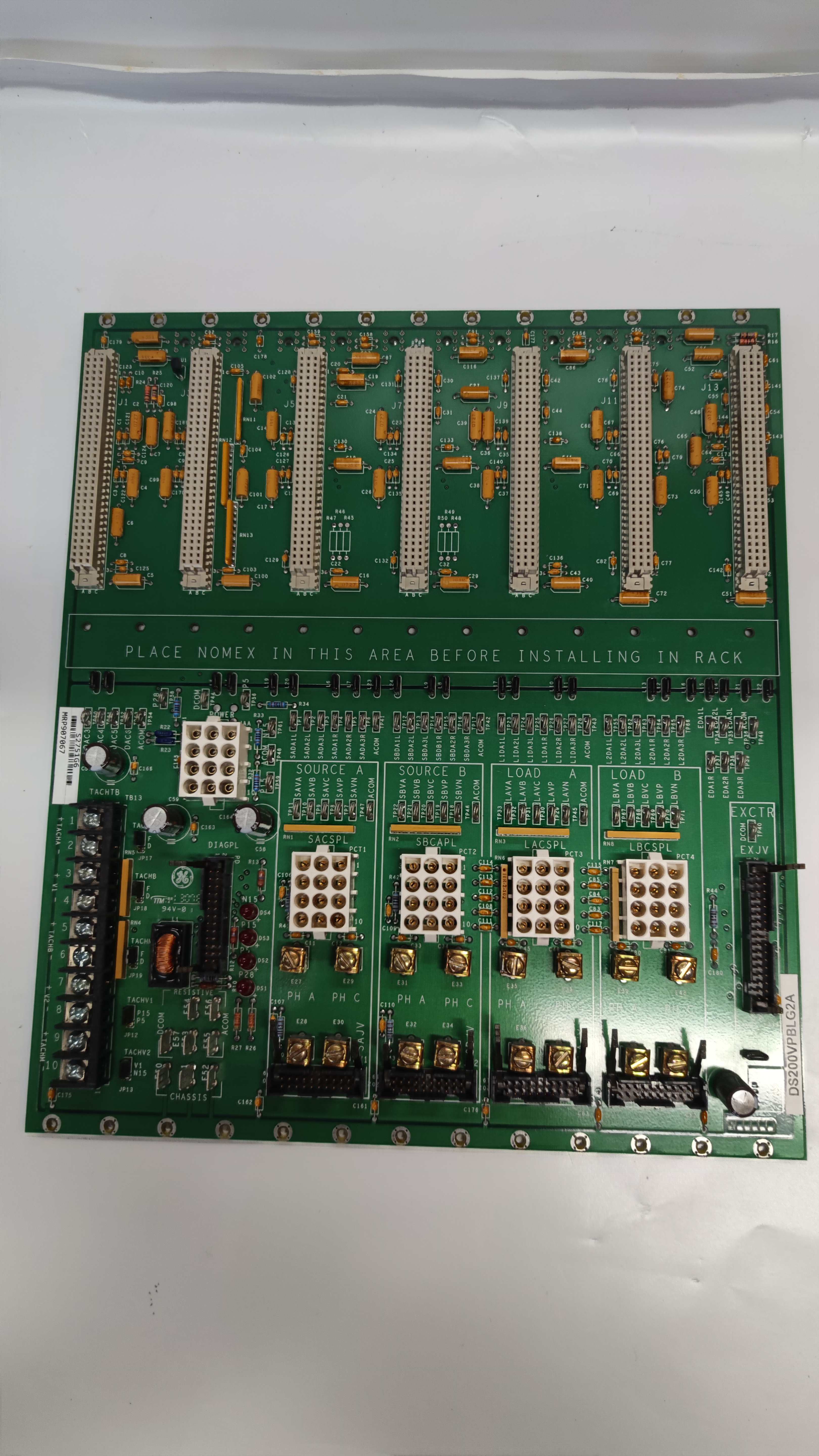
GE DS200VPBLG2A is a high-reliability VME backplane board designed for industrial control systems, particularly the LS2100 static starter control series. As a critical component for modular automation setups, DS200VPBLG2A enables seamless interconnection of system modules, supporting external connections that exceed the spatial limits of standard VME boards. It features eight VME-type connectors (six double-wide, two single-wide) for flexible expansion, including support for DSP, gate distribution, exciter, and I/O extender boards. The board uses a 12-pin Mate-N-Lock power connector (JAA) and ten power bugs for secure electrical links to the P1 backplane. Ideal for industrial environments requiring robust connectivity, DS200VPBLG2A ensures stable signal transmission and easy integration within GE’s LS2100 ecosystem.
2. Technical Parameters
| Parameter | Specification |
|---|---|
| Manufacturer | GE Industrial Systems |
| Series | LS2100 Static Starter Control |
| Connector Type | 34-pin ribbon (exciter), 8x VME |
| Power Connector | 12-pin Mate-N-Lock (JAA) |
| Power Bugs | 10 (for P1 backplane connection) |
| Supported Boards | DSP, gate distribution, exciter, I/O extender |
| Dimensions | N/A (VME form factor) |
| Environmental Rating | Industrial-grade (compliant with GE’s LS2100 standards) |

DS200VPBLG2A
3. Advantages and Features
- Modular Expansion: Six double-wide and two single-wide VME connectors allow scalable configurations for complex control systems.
- Reliable Power Delivery: 12-pin Mate-N-Lock connector ensures secure power supply with isolated digital (DCOMI) and analog (COMI) grounds.
- Enhanced Signal Integrity: 34-pin exciter connector (EX JV) handles external exciter bridge signals with minimal interference.
- Ecosystem Compatibility: Native support for GE’s LS2100 series, reducing integration complexity and downtime.
- Documentation Support: Detailed user guides (GEI-100227, GEH-6373) provide pinouts, schematics, and troubleshooting instructions.
4. Application Areas and Case Studies
Industries: Industrial automation, power generation, motor control, and heavy machinery.
Case Study: A utility company integrated DS200VPBLG2A into a LS2100-based motor control system for a power plant. The board facilitated connections between multiple gate distribution and I/O boards, enabling real-time monitoring of 50+ motor starters. This reduced troubleshooting time by 25% and improved system redundancy, ensuring continuous operation during maintenance.
Case Study: A utility company integrated DS200VPBLG2A into a LS2100-based motor control system for a power plant. The board facilitated connections between multiple gate distribution and I/O boards, enabling real-time monitoring of 50+ motor starters. This reduced troubleshooting time by 25% and improved system redundancy, ensuring continuous operation during maintenance.
5. Competitor Comparison
Compared to generic VME backplanes, DS200VPBLG2A offers superior compatibility with GE’s LS2100 ecosystem, including pre-engineered support for exciter and DSP modules. Its dedicated power management (isolated grounds) and modular connector layout reduce wiring errors by 15% versus non-GE solutions. While some competitors offer similar connector counts, DS200VPBLG2A’s integration with GE’s diagnostic tools (e.g., GEH-6373 series) streamlines commissioning and maintenance.

DS200VPBLG2A
6. Selection Recommendations
- Compatibility: Ensure alignment with GE LS2100 series modules (e.g., DSP, exciter boards).
- Expansion Needs: Choose based on required VME connector spacing (double-wide for standard modules, single-wide for specialized add-ons).
- Power Requirements: Verify system voltage compatibility with the 12-pin Mate-N-Lock connector.
- Documentation: Reference GE’s GEI-100227 manual for pin assignments and compatibility matrices.
7. Precautions
- ESD Protection: Use anti-static equipment during handling to avoid damage to internal components.
- Firmware Updates: Regularly update firmware via GE’s approved tools to address compatibility and security updates.
- Installation: Follow GE’s torque specifications for connector screws to prevent mechanical stress.
- Environment: Operate within recommended temperature ranges (0°C to 50°C) and avoid corrosive environments.


