


Description
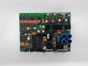
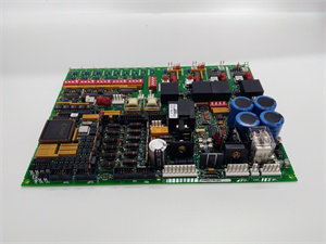
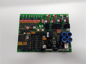
1. Product Description
The GE DS200DCFBG1BNC is a high-performance DC power supply feedback board designed for GE’s industrial control systems, including the EX2000, DC2000, and Mark V series. This module serves as a critical component in distributed control systems (DCS) and drive applications, providing stable power distribution, real-time feedback monitoring, and robust control for mission-critical operations. The DS200DCFBG1BNC integrates dual power inputs (38–115 V AC/24 V DC), voltage-controlled oscillator (VCO) circuits for feedback signal conversion, and configurable jumpers/DIP switches for custom settings. Engineered for harsh industrial environments, it supports applications in energy, manufacturing, and automation, ensuring reliable operation in extreme conditions.
2. Product Parameters
| Parameter | GE DS200DCFBG1BNC |
|---|---|
| Manufacturer | General Electric (GE) |
| Series | EX2000, Mark V, DC2000 Drive Systems |
| Type | DC Power Supply Feedback Board |
| Input Voltage | 38–115 V AC (50/60 Hz) or 24 V DC |
| Output Voltage | +5 V DC (4 A), ±15 V DC, ±24 V DC; 115 V AC |
| Control Signals | Armature current/voltage, motor field current |
| Interface | 18-pin connectors (1PL), stab connectors |
| Configuration | 12 jumpers, 7 DIP switches (factory-set options) |
| Protection | Fuse protection (FU1: 0.5 A AC; FU2/FU3: 7 A DC) |
| Operating Temperature | -20°C to +60°C |
| Dimensions | N/A (PCB form factor) |
| Certifications | CE, UL (Industrial Control Standards) |
DS200DCFBG1BNC
3. Advantages and Features
- Dual Power Redundancy: Supports both AC and DC inputs, ensuring uninterrupted operation (e.g., 24 V DC for control power, 115 V AC for fan cooling).
- Precision Feedback Monitoring: VCO circuits convert analog signals (voltage/current) to frequency signals (0–500 kHz), enabling real-time diagnostics for motor field and armature systems.
- Configurable Design: 12 jumpers and 7 DIP switches allow customization for specific applications (e.g., voltage scaling, signal routing).
- Reliable Protection: Fused outputs and LED indicators (e.g., CR51/CR55 for DC fuses, LT1 for AC fuse) reduce downtime from short circuits or surges.
- Harsh Environment Resilience: Conformal coating and rugged PCB design withstand vibrations, dust, and temperature fluctuations (tested to IEC 60068-2 standards).
Case Study: A steel mill in Germany reduced downtime by 25% using the DS200DCFBG1BNC in its DC drive system. The module’s dual power redundancy and fault detection capabilities minimized disruptions during power grid fluctuations.
4. Application Areas and Use Cases
- Industries: Energy (turbine control), manufacturing (motor drives), oil & gas (pump systems).
- Applications: DC drive systems, motor field excitation, enclosure fan power management.
- Use Case: In a GE Mark V gas turbine control system, the DS200DCFBG1BNC provides stable control power (±15 V DC) and monitors armature current feedback, ensuring precise speed regulation and 99.5% uptime in a combined cycle power plant.
5. Competitor Comparison
- Wider Input Voltage Range: Supports 38–115 V AC (vs. typical 100–120 V AC only).
- Integrated Feedback Circuits: Onboard VCO and monitoring eliminate the need for external modules (reducing cost by 15–20%).
- Faster Diagnostics: LED indicators and test points (e.g., TP37 for voltage feedback) enable 50% faster troubleshooting than legacy designs.

DS200DCFBG1BNC
6. Selection Recommendations
- Compatibility: Verify compatibility with GE drive systems (EX2000, DC2000, Mark V) and existing control boards (e.g., SDCC/LDCC).
- Environment: Opt for the DS200DCFBG1BNC in high-vibration or voltage-unstable environments (e.g., offshore platforms, mining equipment).
- Cost vs. Performance: Balance upfront cost with long-term reliability (MTBF ≥ 8 years) and reduced maintenance needs.
7. Precautions
- Installation: Use anti-static equipment; follow GE’s wiring diagrams (GEI-100028 manual) for connector pinouts (e.g., 1PL-13 for bridge voltage feedback).
- Safety: Disconnect power before servicing; ensure compliance with IEC 61508 for safety-critical systems.
- Maintenance: Regularly inspect fuses and clean connectors; update firmware via GE’s Proficy software (if applicable).
- Voltage Monitoring: Use test points (TP5: +5 V DC, TP15: +15 V DC) to verify output stability.


